RF Front-End Mini
A smaller version of the RF Front-End for single-input single-output (SISO) operation. Please see the original RFE documentation for details of the features and operation, as the RFE Mini is largely the same, albeit single channel and controlled via a Raspberry Pi Pico instead of an STM32 MCU.
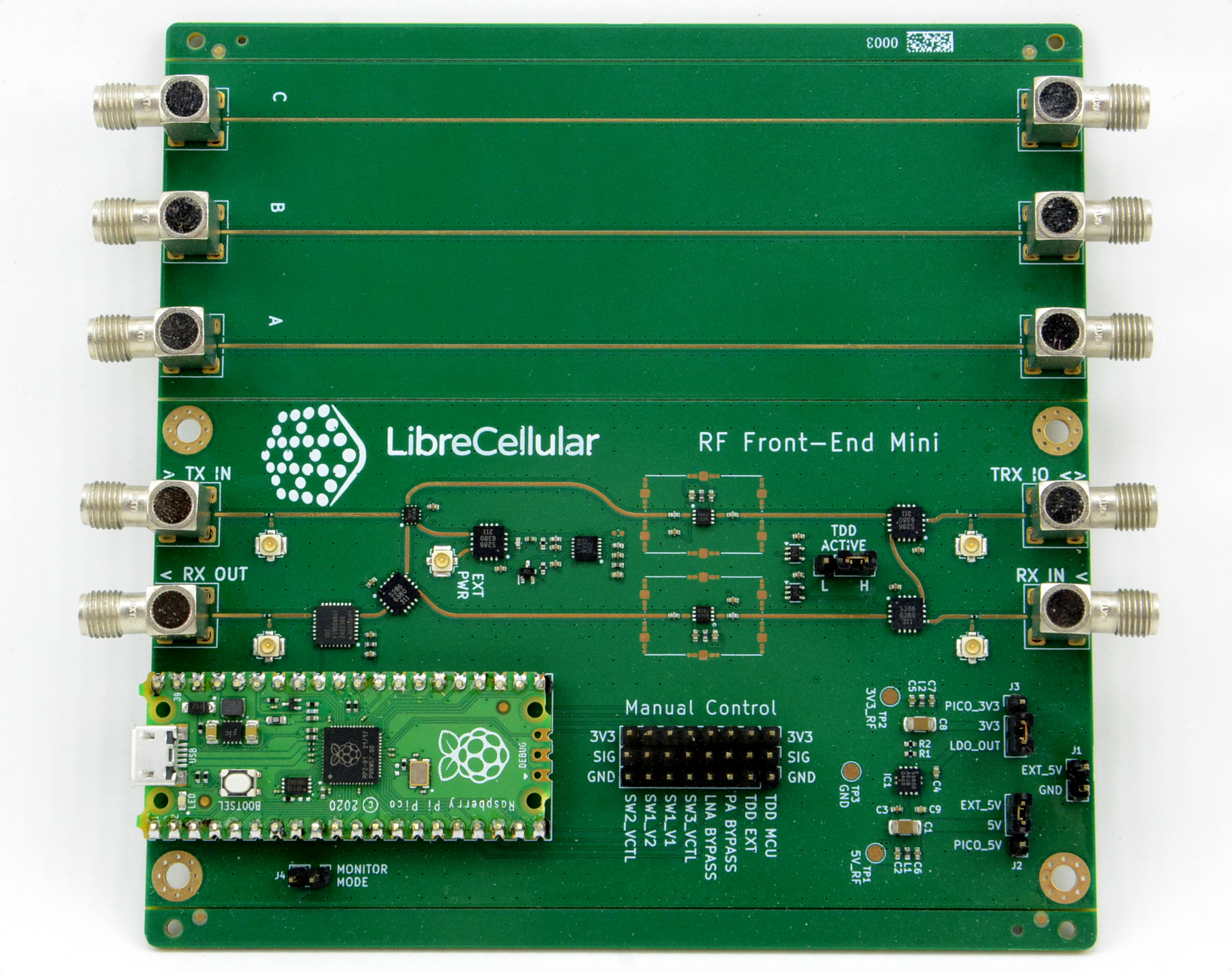
The RFE Mini design was originally created as a lower cost platform for validating and optimising the RF layout of the larger 2x2 RFE. It makes use of a Raspberry Pi Pico for control and this is programmed using CircuitPython, as this enables faster iteration and development of test scripts.
Note that the RevA1 design pictured incorporates three coplanar waveguide transmission lines for characterisation purposes. In addition to which manual control of RF switches was possible using jumpers. However, these will all ve removed from the RevA2 design, which is currently a work in progress.
Specifications
MIMO |
2T2R |
Frequency range |
500MHz - 4GHz |
Insertion loss |
TBC |
LNA and PA gain |
19 dB (see below) |
LNA and PA P1dB |
21.2 dBm |
Receive attenuation |
0-31.75 dB |
RF power measurement |
-34 dBm to 6dBm |
Board power supply |
5 VDC (USB 2.0) |
Power supply for switched DC outputs |
12-28V |
Switched DC outputs (per port) |
12-28V (dependent upon input voltage) @ 3A / 12V @ 2A / 5V @ 2A |
Note
Assembled boards have not been fully characterised yet, the gain figure quoted is for the Qorvo TQL9063 part used for the LNA and PA, and there will be insertion loss and likely also reduced performance at higher frequencies due to the use of FR4 PCB substrate in the initial design.
Design
The PCB design has been entered using KiCAD and for details, see the RFE Mini Hardware GitHub repository.
Firmware & Software
For the RFE control firmware and software see the RFE Control GitHub repository.
Credits
LibreCellular RFE schematic capture, board layout, firmware and software development by Ordinatra Minima.